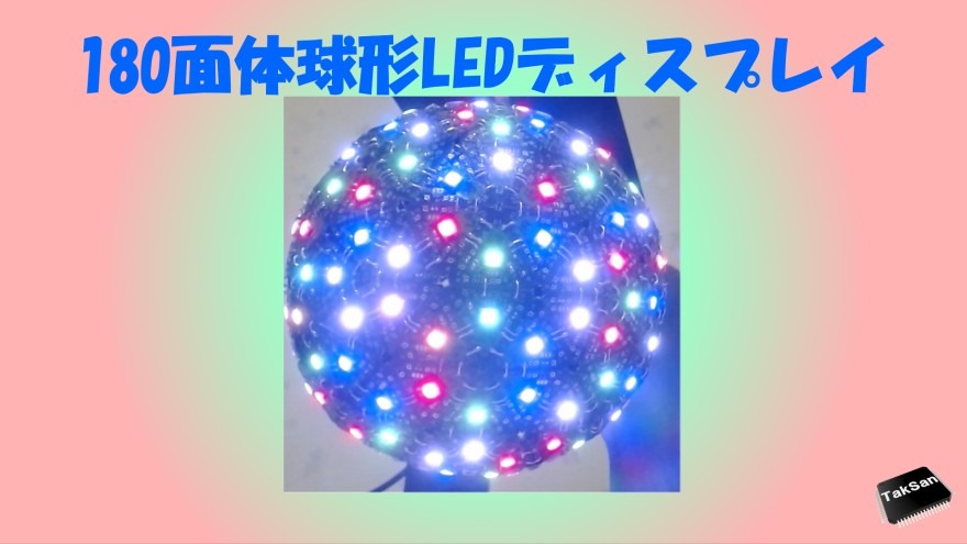
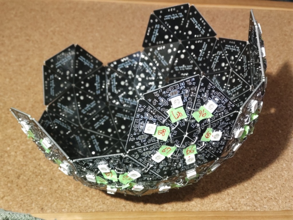
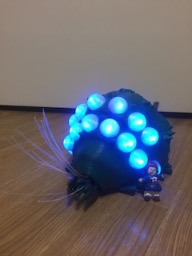
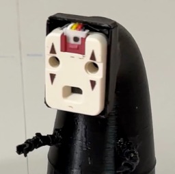
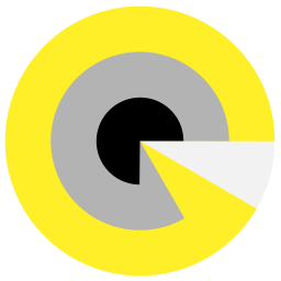
180面体球形LEDディスプレイ
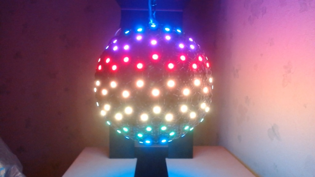
完成
© CC BY 4+
3370
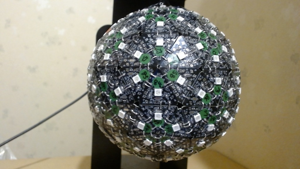
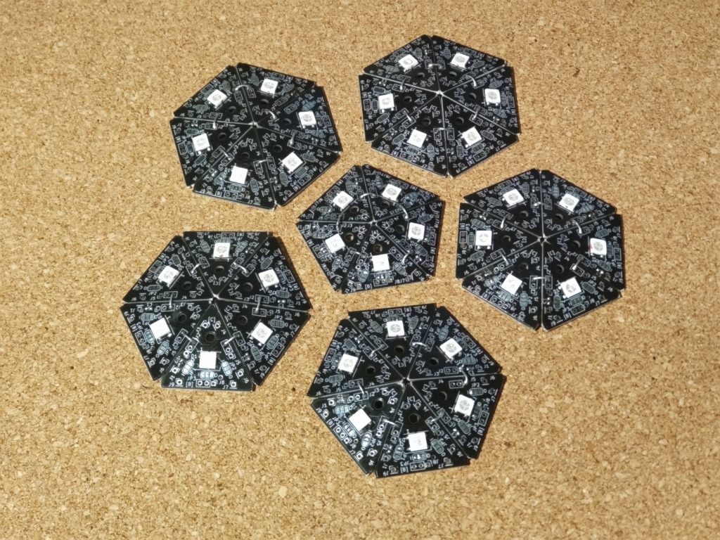
180面体で構成された球体LEDディスプレイです。各面に1つの Neopixel LED が付いています。
-
 特別賞Mouser Make Awards 2023
- 動画
-
- 開発素材
-
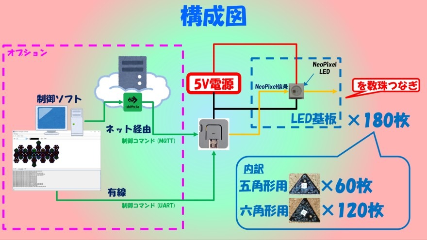
- システム構成
-
- ストーリー
-
- メンバー
-
-
- TakSan @taksan
-
-
- 関連イベント
-
-
 Mouser Make Awards 20232023-05-01 開催
-
 ヒーローズ・リーグ 20232023-08-28 開催
-
 M5Stack Japan Creativity Contest 20232023-07-15 開催
-
 「Maker Faire Tokyo 2023」の出展作品まとめ(一部だよ|非公式だよ)2023-10-14 開催
-
 テックシーカーコレクション20242024-07-06 開催
-
 つくろか!3 〜よみがえれ、ものづくり百鬼夜行〜2024-10-26 開催
-
- 関連リンク
-

-
-
-
- 同じニオイがする作品
-
-
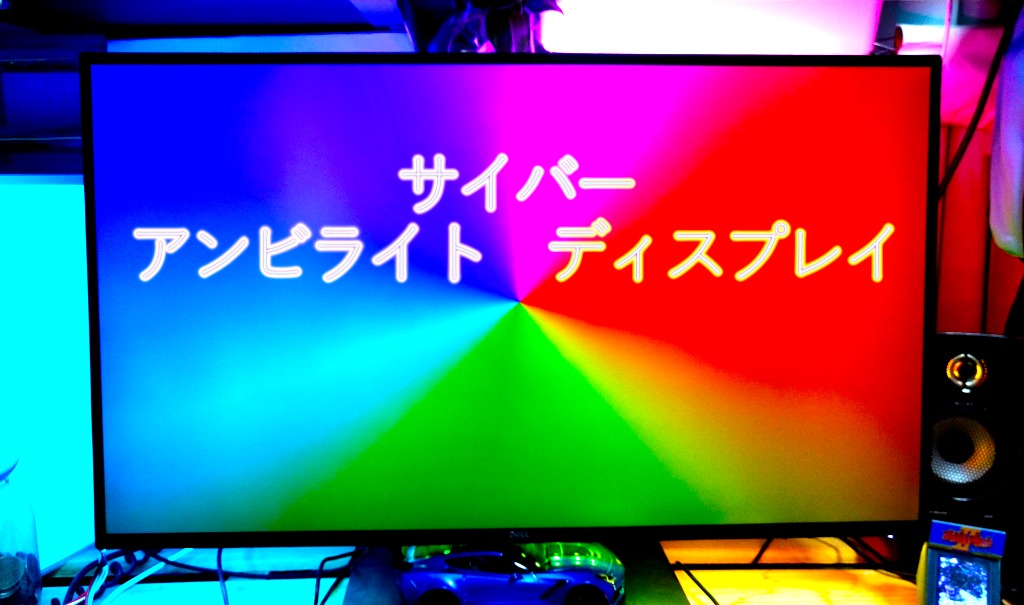 サイバー アンビライトディスプレイ
-
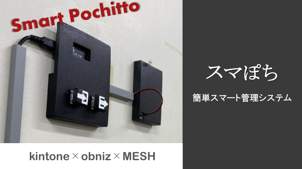 【簡単スマート管理システム】スマぽち
-
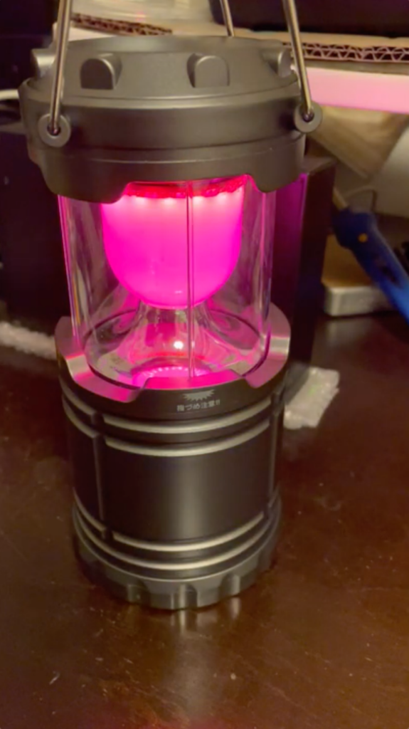 虫ではなく人を寄せ付けるゲーミングランタン(IoT仕様)
-
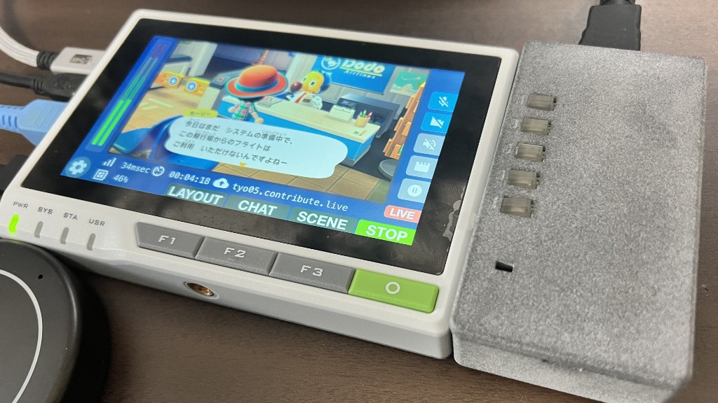 reTerminalとHDMI入力でゲーム配信! - HDMI入力拡張モジュール -
-
Proto lovers ♥


Techseekerで近くでミニ百葉箱を展示しておりました。
球体LEDディスプレイすごいですね。
ライフゲームのグライダーを飛ばしてみたくなりました。
コメントありがとうございます。
「ミニ百葉箱」噂には聞いていて気にはなっていましたが、Techseekerは展示で4作品にハッカソン参加と欲張りすぎの多忙で殆どブースを回れずでした…近くだったんですね。
「ライフゲームのグライダー」知らなかったんですが、なるほど面白いです。
マウザーコンテストの発表を聞いていました.180という数の多さをのりきるためのなみなみならぬ努力が素晴らしかったです.
<最終審査員が選出>池澤さん:基盤の発注からフルカラーLEDの実現までの熱量がすごい。球体設計の工夫と苦労の話が興味深く、お話しがとても面白かったです。(講評を事務局が代筆)