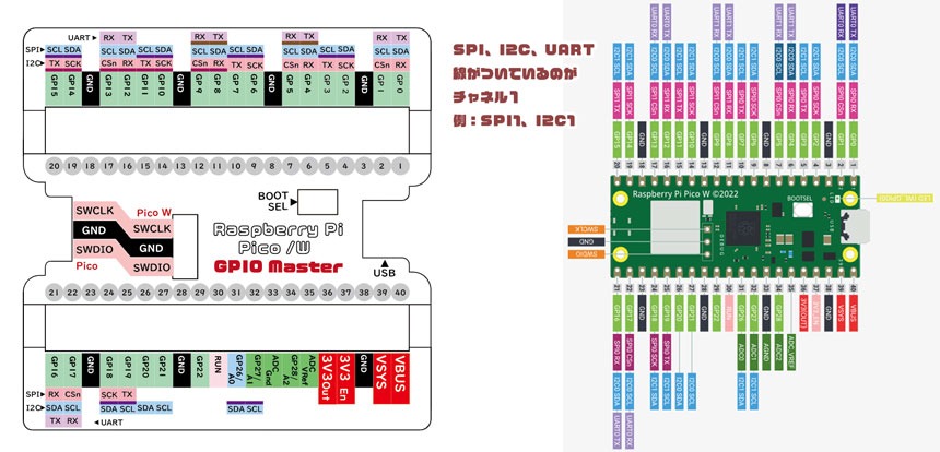
Raspberry Pi PicoやRaspberry Pi Pico Wをブレッドボードで配線する場合に苦労すること。
それは、「どのGPIOに配線するのか基板を見ただけではわからない」ことですよね。
GPIOの配置は、資料として公開されているので、資料を見ながら、Raspberry Pi Picoの向きを合わせて、GPIOを確認しながら、配線していく・・・
そうして時間がかかったり、間違った配線をしてしまうことも多いですよね。
そんなとき、この「GPIO Master」があれば、Raspberry Pi Picoに上から取り付けるだけで、GPIOの番号や役割について確認しながら配線できるようになります。
これで、資料との見比べなしに、確実な配線ができますよ~。
~English~
Difficulties when wiring Raspberry Pi Pico or Raspberry Pi Pico W with a breadboard.
The problem is that you can't tell which GPIO to wire just by looking at the board.
The placement of GPIO is published as a document, so while looking at the document, align the orientation of the Raspberry Pi Pico, check the GPIO, and wire it...
Doing so takes time and often results in incorrect wiring.
In such a case, if you have this "GPIO Master", you can simply attach it to the Raspberry Pi Pico from above and wire it while checking the GPIO number and role.
Now you can make sure wiring without comparing with the documentation.
作品のこだわり
Raspberry Pi PicoとRaspberry Pi Pico Wの両方で使用できるように設計しています。
ブレッドボードと、Raspberry Pi PicoのGPIO、このツールの表記を合わせてみることができるように、役割を記載している箇所の高さをRaspberry Pi Picoの基板よりも低く設定しています。 これにより、横斜め上から見た際に配線がしやすくなっています。
また、Raspberry Pi Picoは、SPI、I2C、UARTにおいて2つのチャネル(SPI0、SPI1)などを持っています。 グッツの小さいスペースでその違いを表すため、「SPI1」など1番のものは濃い直線を表記に追加して、視認しやすくしています。
~English ~
Attention to detail
Designed to be used with both Raspberry Pi Pico and Raspberry Pi Pico W.
In order to match the descriptions of the breadboard, Raspberry Pi Pico's GPIO, and this tool, the height of the part where the roles are described is set lower than the Raspberry Pi Pico's board. This makes wiring easier when viewed diagonally from above.
Raspberry Pi Pico also has two channels (SPI0, SPI1) for SPI, I2C, and UART. In order to express the difference in the small space of the goods, we added a dark straight line to the number 1 item such as "SPI1" to make it easier to see.
下記のBOOTHショップで販売していますので、良ければどうぞ!
設計は、3DCADを作成し、3Dプリンター「Original Plusa i3KM3S+」を使用して造形しました。
下記のBOOTHショップで販売していますので、良ければどうぞ!